Dx-200 Digital Switching System Specification Summary
DX-200 Nokia is a modular-based hardware and software digital switching system.
It is controlled by software using distributed controlling devices. Control is distributed by modules (SSP, SSU) and functions (RU, M, LSU, MFCU, CM, STU, OMC, CCSU).
DX-200 was manufactured by TELENOKIA, Finland.
Nokia DX 200 Digital Switching Platform is designed to be operated as a terminal exchange and terminal and transit exchange with local telephone networks (TE, TTE) and to organize transit nodes.

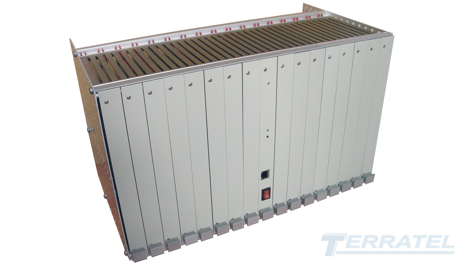
Pic 1. DX-200 NOKIA System appearance.
Upgrade, migration and integration of the system DX-200 Nokia IP, IMS, NGN and VoIP networks.
DX-200 can operate using both the full numbering scheme (5-digit, 6-digit and 7-digit numbering scheme) and reduced numbering scheme of the local subscriber number.
By the time DX-200 Nokia was designed and implemented it had featured the following advantages:
- modular-based hardware and software;
- reliable operation of the exchange equipment;
- automated operating processes;
- wide selection of value added services;
- interaction with all existing Telephone Exchange types;
- application of SS7;
- use of remote equipment (concentrators and sub-exchanges).
DX-200 had DX-210 and DX-220 modifications that were used with local PSTN telephone networks.
DX-210 was used to build exchanges of small and medium capacity.
DX-200 was used to build large capacity exchanges.
DX 200 Nokia General Specification
Total number of subscriber lines (SL) in Telephone Exchange – 100,000
Total number of circuits in Telephone Exchange – 57,000
Total capacity – 22,800 Erlangs
Power consumption per line – 1W
Number of different types of standard exchange items – 30
INTEL x86 processors
Cabinets/Telephone Exchange 20,000 lines – 20
Square/20,000 lines – 40 sq.m
Hardware failures/year/10,000 lines – 50
Supported signalings – SS7, EDSS-1 (2B+D, 30B+D), V5.2, R2, MFC, MFP (R1.5+Automatic Number Identifier)
DX-200 Nokia Value Added Services
The following value added services were implemented in DX-200:
- abbreviated dialing
- direct calling
- outgoing or incoming call barring
- call charging
- forwarding
- fraudulent subscriber detection
- conference calls etc
About 20-30% of subscribers of this Telephone Exchange can use value added services.
DX 200 Nokia Subscriber Equipment
Subscriber equipment is a set of subscriber selection units comprising the following components:
- SUB subscriber modules and SSP controlling devices for subscriber modules
- RSUB remote subscriber equipment
- Digital switching network of the Subscriber Selection Unit or SSW subscriber switching stage
- SSU Subscriber Selection Unit controlling device
SUB DX 200 Nokia Subscriber Modules
All subscriber lines are combined into groups of 64 subscriber lines that are included in SUB via subscriber sets.
SUB subscriber modules feature the following parameters: 64 physical subscriber lines at SUB input and 1 PCM line (32 time channels) at SUB output, i.e. concentration is 2:1. Specific load per 1 subscriber line does not exceed 0.15 Erlangs.

Pic 2. Subscriber Modules SUB DX-200
The number of SUBs within a single subscriber selection unit does not exceed 64, however the cabinets can accommodate 58 SUBs as maximum. The SUB performs space and time switching and converts analog signals to digital signals and backwards. The number of SUBs depends on Telephone Exchange capacity only.
Each SUB is connected to SSW with a single PCM line. The 16-th time channel of this PCM line provides communication between SSP and SSU.
The SUBs that are intended to include common subscribers are equipped with 4 SUB boards and each such board accommodates 16×16 subscriber sets. The SUB is controlled by a subscriber unit controlling device (SSP). The SSP functions include scanning control points of the subscriber set within the unit; receiving address information in a decade code and transmitting it to SSU over the 16-th time channel; connecting RGU call generator (25Hz, 80V) to the subscriber set to generate the “call sending” signal for the subscriber.

Pic 3. Subscriber line SLU 8C
DX-200 also had dedicated SUBs intended to connect the payphone equipment.
These dedicated SUBs were equipped with 8 SUB8 boards and each such board had 8 subscriber sets.
To connect remote subscriber groups DX-200 was equipped with remote subscriber units (RSUB) that were connected to SSW switching network via ET common exchange sets.
DX-200 imposes strict requirements to the temperature and humidity of the room requiring air conditioning in the room, which increases the cost of the Telephone Exchange equipment and expenses for its further maintenance.
DX 200 Nokia Equipment Block Diagram

Pic 4. DX 200 Nokia Equipment Block Diagram
The general block diagram of DX-200 fully equipped with DX-200 equipment is as follows:
SUB – Subscriber Unit
GSW – Group Switching Stage
SSW – Subscriber Switching Stage
SSP – Subscriber Unit Controlling Device
SSU – Subscriber Switching Stage Control Unit
LSU – Line Signaling Unit
M – Marker
RU – Register Unit
CM – Central Memory
OMC – Operation Maintenance Computer.
iSUB Access Gateway ->
Solution for Upgrading and Integrating DX-200 Nokia to IP VOIP/NGN/IMS Networks.
DX-210 Nokia Structure
This version differs in that the switching network of DX-210 Nokia contains only subscriber stages of Subscriber Selection Unit and it includes all exchange sets and subscriber equipment of the exchange. SSU, CCSU, LSU, M, RU, CM, and STU that are parts of DX-220 are integrated within DX-210 into a single backup electronic control machine for processing calls (CAC) that is responsible for establishing connections.

Pic 5. DX-210 Nokia Structure
V5.2 Interface in DX 200 Nokia and DX 220 Nokia
Connecting access equipment over V5.2 interface. DX 200 and DX 220 platforms were designed in accordance with technical requirements of digital Telephone Exchange to provide services of V5.1 and V5.2 open interfaces. V5 interface provides the opportunity for the operator to build the access network regardless of the manufacturer of the local Telephone Exchange. V5 interface allowed the operator to offer plain old telephone services (POTS) and ISDN services for both wired and wireless access solutions.
V5.2 to SIP VoIP Gateway ->
Solution for Integrating AN Subscriber Access Equipment into IP Networks.