R2 MFC to SIP Gateway or Signaling Converter

Features
- up to 16 E1 interfaces
- up to 480 VoIP channels
- SS7, ISDN PRI (DSS1, QSIG, Q.931), V5.2, R2 CAS, R2 MFC, R 1.5
- SIP, SIP-I, RTP, RTCP, TCP, UDP
- Voice codecs – G.711 (a-law, µ-law), G.723.1, G.726, G.729a/b, GSM
- Voice quality – Adaptative jitter buffer, VAD, SID, CNG
- Registration and authentication – up to 10000 SIP-subscribers
- Fax over G.711, T.38 fax relay
- Echo Cancellation
- Call Routing TDM-SIP, SIP-TDM, TDM-TDM and SIP-SIP
- SNMPv2 monitoring
- RADIUS login
- Security (іntegrated firewall, password protected access, SSH)
- Single/Dual-redundant 220 VAC or 48/60 VDC Input
Overview
The R2 MFC VoIP Gateway is designed for the reconstruction and integration of telecommunications TDM equipment with support for R2 signaling system (type CAS) in IP, IMS and NGN networks.
R2 VoIP Gateway, thanks to the implementation and support of R2 MFC signaling is an optional product of the Terratel SIP/E1 Gateway model.

Pic 1. SIP to R2 MFC Gateway Connection Block Diagram.
R2 MFC (Multi-Frequency Compelled) signaling is a Channel Associated Signaling (type CAS) protocol.
R2 VoIP Gateway from Terratel can smoothly combine subscriber access networks and TDM digital switch nodes with next generation IP networks by converting SIP and R2 MFC signaling.
An additional function of this product is the conversion of the R2 MFC signaling to SS7 or ISDN PRI.
Functionality
- Supports R2 MFC signaling system
- Supports integrated IP-PBX functions
- Simultaneously supports SS7, ISDN PRI, V5.2 and R2 CAS signaling within a single device
- Provides for combining several PBXs into a corporate network with internal dialing plan
- Provides for integrating IP-TDM-IP, TDM-TDM and IP-IP connections
R2 MFC Digital Signaling System
R2 signaling is a channel associated signaling (type CAS ) system developed in the 60 years of the last century and that is still in use today in Europe, Latin America, Australia, and Asia.
R2 MFC (R2 Multi-Frequency Compelled) signaling is a Channel Associated Signaling (type CAS) protocol used over E1 signaling networks.
R2 MFC is used to convey addressing information along a telephone trunk between two digital switches in order to establish a telephone connections.
Specifications of the R2 signaling system are defined in ITU-T Recommendations Q.400-Q.490
R2 MFC – Compelling signaling. In the E1, CAS protocols use timeslot 16 for line signaling (also called supervision) – on hook, off hook, etc.
Dual tones representing digits are used for called and calling numbers, sometimes called ANI and DID.
R2 VoIP Gateway supports the digital version of line signals and inter-register signals.
R2 signaling from switch to switch supports the following MFC call types:
- Simple calls (Incoming and outgoing calls): This is the signaling used between a PBX and a Central Office for local calls and toll free call
- Calls with Caller ID: This is used between central offices for tracking the call to report the number to the switch being called and to apply billing charges when necessary
Configuring and Settings R2 signaling protocol
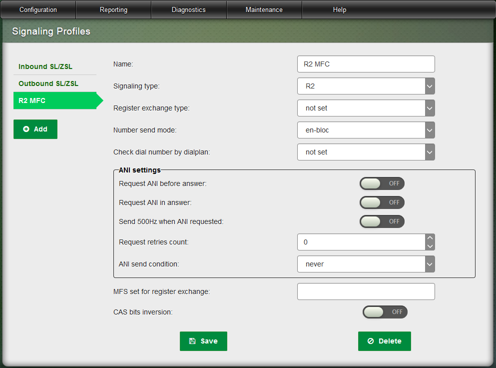
When organizing two-way lines with R2 MFC signaling type you should set the parameters specific to CAS protocol to their required values in addition to setting parameters common to all signaling types:
- Register exchange type
- CAS bits inversion
For outbound connection you should set the following additional parameters to their required values:
- Request ANI before answer
- Request ANI in answer
- Send 500Hz when ANI requested
- Request retries count
- MFS set for register exchange

Pic 2. Web Interface – Configuring and setting R2 MFC signaling protocols.
For inbound connection you should set the additional parameter ANI Send Condition to its required value.
ANI – specific CID (Caller ID) version for Eastern Europe.
Integration of R2 Signalling System with SoftSwitch
We offer the gateway for upgrading telephone networks featuring multiple R2 MFC Signaling.
There are 2 options for using this gateway based on tasks to be solved.
Option 1 is used when it is required to replace the TDM Digital Switch with the SoftSwitch. If multiple subscriber nodes are connected to the TDM Digital Switch over the R2 MFC Signaling they can be switched to the SoftSwitch using the gateway as indicated on the following figure.

Pic 3. Network Diagram of the R2 MFC VoIP Gateway to the Softswitch and the Subscriber Digital Line Concentrator.
In this case the R2 interface disconnects from the TDM Switch and connects to the gateway that is connected to the SoftSwitch via the SIP data communications network.
Integration of SIP subscribers through R2 signaling
Option 2 is used when it is required to connect VoIP subscribers from the local network to the PSTN number capacity. If the operator has the existing TDM Switch with free R2 interfaces the gateway on the TDM network side looks as the R2 subscriber node while on the IP network side it looks as the IP PBX where IP subscribers register (please see the figure).

Pic 4. Incorporating R2 MFC VoIP gateway to TDM switch and IP network network Diagram.
R2 MFC protocol conversion option
Since the gateway supports SS7, ISDN PRI, V5.2 and R2 MFC signaling it can be used as a protocol converter.
This is important when TDM networks are upgraded and it is required to adapt various telecommunications products to R2 MFC interface protocols.

Pic 5. Network diagram of using the device as a signal converter R2 MFC and SS7.
R2 MFC VoIP gateway from the company Terratel is used in different options of conjugation of VoIP and TDM/PSTN networks for minimization of expenses and reduction of operational costs.
Signaling System R2 MFC (Multi Frequency Compelled R2)
R2 MFC is a telecommunications signaling protocol that is used to transmit exchange information between two telephone switching systems to establish a telephone call over a telephone line.
Logically, R2 MFC is divided into two protocol groups (line signals and address signals).
R2 MFC was used to transmit signals over both analog and digital channels.
The R2 signaling specifications are described in Recommendations Q.400–Q.490 (ITU-T).
The R2 MFC signaling methods are logically divided into two protocol groups. The line signaling group includes control signals for call establishment and termination (line signaling), while the interregister signaling uses in-band multi-frequency signals to transmit address information of the calling and called parties (address signaling).
Technical Specifications
| Network Interfaces | |
|---|---|
| TDM | up to 16 E1 interfaces |
| SIP and RTP | up to 480 VoIP channels, 10/100/1000 BASE-T Ethernet |
| Management | Fast Ethernet, RS-232 |
| Signaling Protocols | |
|---|---|
| IP | SIP, SIP-I, RTP, RTCP, TCP, UDP |
| PSTN | SS7, ISDN PRI (DSS1, QSIG, Q.931), V5.2, R2 MFC, R2 CAS, R1.5 |
| Feature Support | |
|---|---|
| Voice codecs | G.711 (a-law, µ-law), G.723.1, G.726, G.729a/b, GSM |
| Voice processing | Adaptative programmable jitter buffer, VAD, SID, CNG |
| DTMF | RFC2833, SIP INFO, RFC 2976 |
| FAX | fax over G.711, T.38 fax relay |
| Echo Cancellation | G.168 up to 128 ms |
| Registration and Authentication | up to 10000 SIP-subscribers |
| Registration | SIP-trunks |
| Call Routing | TDM-SIP, SIP-TDM, TDM-TDM and SIP-SIP |
| Power | |
|---|---|
| Single/Dual-redundant 220 VAC or/and 48/60 VDC Input | |
| Up to 28W Power consumption (for 16 E1) |
| Operations Management | |
|---|---|
| GUI via Embedded Web Server | |
| SNMPv2 monitoring | |
| Syslog Telnet (for CLI) |
| Security | |
|---|---|
| Integrated firewall, Password protected access, SSH, RADIUS login |
| Operating Environment | |
|---|---|
| Operating temperature | from 0°С to +60°СHumidity |
| Humidity | up to 80% at +25°С |
| Hardware | |
|---|---|
| System Type | Board |
| Dimensions | 1U high, 19″ wide rack mountable |
Delivery Set
SIP/E1 Gateway Lite:
- SIP/E1 Gateway Lite (1Е1, 30 SIP channels, G.711, T38 codecs, echo cancellation G.168)
SIP/E1 Gateway:
- SIP/E1 Gateway (2Е1, 240 SIP channels, G.711, G.726, G.729, T38 codecs, echo cancellation G.168)
- SIP/E1 Gateway (4Е1, 240 SIP channels, G.711, G.726, G.729, T38 codecs, echo cancellation G.168)
- SIP/E1 Gateway (8Е1, 240 SIP channels, G.711, G.726, G.729, T38 codecs, echo cancellation G.168)
- SIP/E1 Gateway (12Е1, 240 SIP channels, G.711, G.726, G.729, T38 codecs, echo cancellation G.168)
- SIP/E1 Gateway (16Е1, 480 SIP channels, G.711, G.726, G.729, T38 codecs, echo cancellation G.168)
