SIP E1 Gateway in SFP form factor for integration PSTN and IP networks
Features
-
- 1 E1 interface (G.703)
- SIP and RTP (up 30 VoIP channels)
- SIP, RTP, TCP, UDP
- ISDN PRI (DSS1, QSIG, Q.931), R2 MFC, R1.5
- fax over G.711, T.38 fax relay
- Hardware Echo Cancellation
- Web-interface
- SNMP monitoring
- Network Element Remote Monitoring System
Overview
SFP VoIP E1 Converter is a unique equipment that is used in various options for pairing VoIP and TDM/PSTN networks (for connecting the E1 interface to an IP network). The device is designed to solve problems when the consumer needs to connect only one E1 interface to the IP network.
SFP VoIP E1 Converter can act as a VoIP PRI gateway, VoIP R2D gateway and VoIP R1.5 gateway.
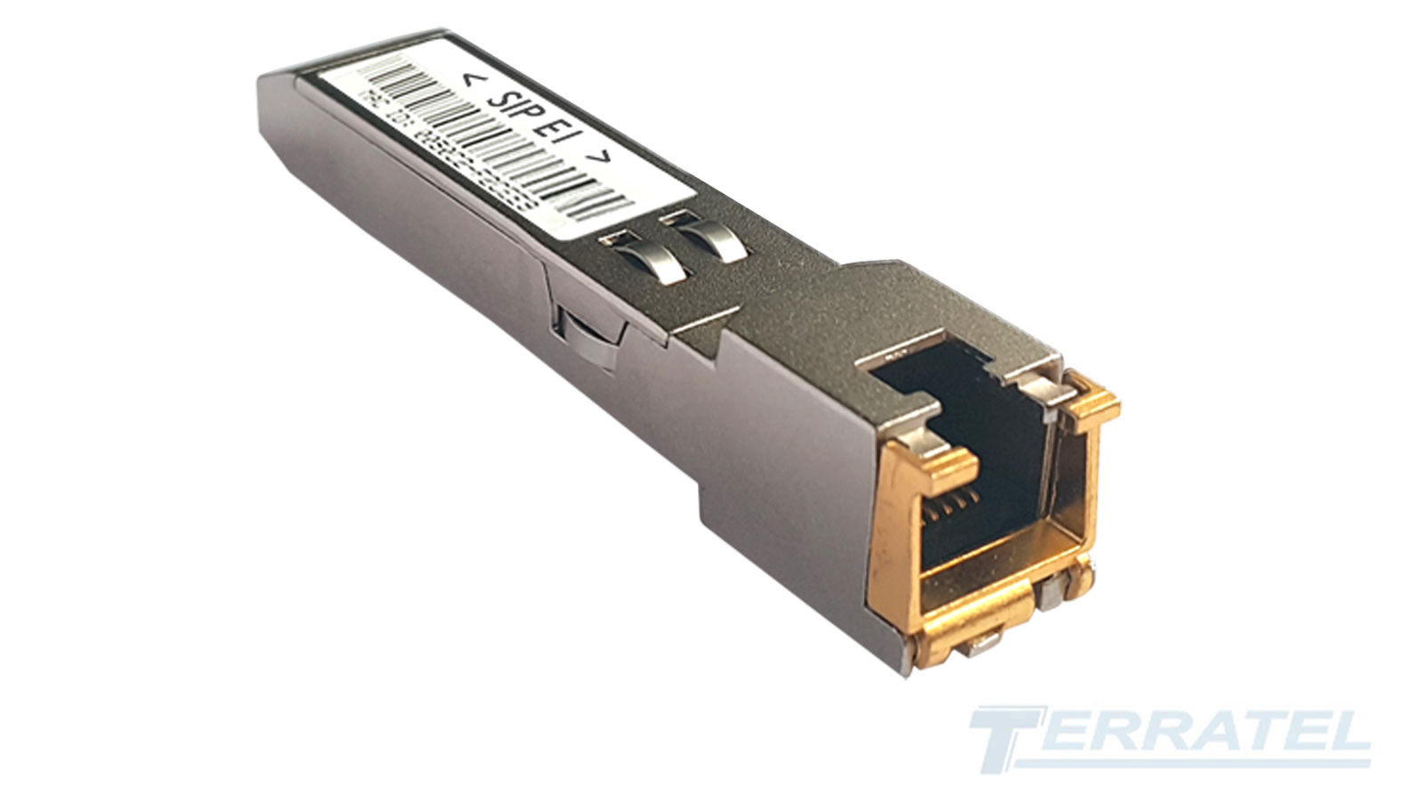
For ease of installation, the module is made in the SFP form factor and can be inserted into any switch or media gateway that has an SFP slot (see photo below) and does not take up additional space.

Рic 1. Sample of connecting SFP VoIP E1 module via Ethernet switch
The support of ISDN PRI (DSS1, QSIG, Q.931), R2 MFC and R1.5 signaling protocols used on the PSTN network allows the equipment to be used for the reconstruction and upgrade of legacy PBX used on the network.

Pic 2. SFP VoIP E1 Converter connect block diagram
Connection to the PBX is through the E1 interface.
Hardware overview (SFP form factor)
The design of SFP VoIP Converter is made taking into account the SFF-8074i specification for devices in the SFP (Small Form-factor Pluggable) form factor.
SFP VoIP Converter provides support for physical Ethernet connection and E1 (G.703) interface.
The module is inserted with an SFP electrical connector into a free SFP slot of the host network device (switch, router or similar equipment).
The device’s SFP electrical connector is designed according to the SFF-8074i specification and provides connection to the network device through ground, power, and signal pins.
The device is powered from the internal board of the network equipment in which the converter is installed (direct current with a rated voltage of 3.3 V), power consumption up to 1 W.
On the other side, the module has an RJ45 connector, intended only for connecting the E1 interface.
This device has a hardware echo cancellation function for all voice channels of the E1 interface.
SFP VoIP Converter supports the hot-swap function of the module, without turning off the power supply to the equipment (hot-swap).
Key Specifications
- Up to 30 simultaneous calls per 1E1 port
- Supports E1 physical interface connections (G.703)
- PSTN protocols support: PRI (DSS1, QSIG, Q.931), R2 MFC, R1.5
- Asterisk interface support
- VoIP protocols support: SIP
- Fax and modem support: Fax over G.711, T.38
- Industry standard RJ-45 port
- SFP form factor
Configuration Signaling PSTN and SIP Trunk
Terratel SFP VoIP E1 Converter supports up to 30 PSTN trunk connections in one E1 interface (PRI, R2 MFC).
In the direction of the IP network, the SFP VoIP E1 converter supports SIP.
For a physical connection to the PBX, the E1 interface is used, and to the IP network is the sfp-slot network equipment.
A simplified list of steps required to integrate the PBX and IP network using the SIP protocol:
- Configure the physical connection of the E1 interface
- Select and configure the desired TDM network signaling system
- Configure SIP protocol
- Restart device
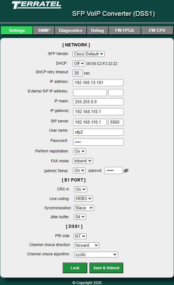
The device is configured in the Settings tab of the Web interface.

Pic 3. Web interface – Device settings on the Settings tab
The list of configurable parameters contains three sections – NETWORK, E1 PORT and DSS1.
Diagnostics and monitoring
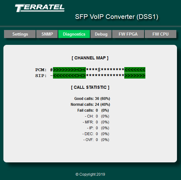
The Diagnostics subsection of the integrated Web interface is designed for real-time monitoring of the status of PCM channels (E1 interface), SIP channels and call statistics.

Pic 4. Web interface – Monitoring the status of PCM channels on the Diagnostics tab
The displayed parameters of the Diagnostics subsection allow you to monitor the status of the device and its operation statistics.
For network monitoring, the device provides an integrated SNMP agent (SNMP v1/v2c). The real-time SNMP agent transmits messages about the incidents to the SNMP manager. Also, the SNMP agent supports monitoring of device states upon request from the SNMP manager.
The value and description of variables provided by the SNMP agent on the device are provided in the corresponding MIB file.
Primary Interface ISDN-PRI. Signaling protocols DSS1, QSIG, Q.931. What is this?
ISDN (Integrated Services Digital Network) is a technology for transmitting Digital and Analog data using a single telephone line, which combines the transmission of voice, data and images.
Primary Rate Interface PRI
The PRI primary speed interface is an ISDN network access that can work with T1 channels (24 channels with a bandwidth of 64 kbit/s, data transfer rate of 1.544 Mbit/s) or E1 channels (data transfer rate of 2.048 Mbit/s).
E1 has 32 channels separated by time. 30 channels are used for voice or data transmission, and 2 channels are used for signal information transmission. Each of the 32 channels has a bandwidth of 64 kbit/s, the total bandwidth of E1 is 2048 kbit/s.
One signaling channel is used for synchronization of terminal equipment, the other is used for transmitting data about the process of setting up connections. E1 is described by the formula 30B+D+H.
Signaling protocols DSS1, QSIG, Q.931
To control ISDN-PRI interface channels that unite telecommunication devices into a single network, signaling protocols such as DSS1, QSIG, Q.931 are used.
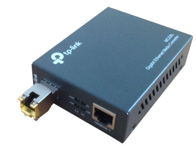
Connecting SFP VoIP E1 module via Ethernet media converter
If during the deployment of the SFP VoIP E1 module for connecting communication systems based on the SIP protocol and devices using the E1 interface it is not possible to connect it to a local area network (LAN), you must use a budget media converter.

Pic 5. Sample of connecting SFP VoIP E1 module via Ethernet media converter
These media converters are designed to convert the signal and then connect the 1000BASE-SX fiber optic cable with a 1000 Base-T twisted pair cable.
Technical specifications
| Network interfaces | |
|---|---|
| TDM – 1 interface E1 (G.703) | |
| IP – Ethernet 1000 BASE-X SFP, 1 SIP trunk | |
| SIP and RTP (up 30 VoIP channel) |
| Signaling protocols | |
|---|---|
| IP – SIP, RTP, TCP, UDP | |
| PSTN – ISDN PRI (DSS1, QSIG, Q.931), R2 MFC, R1,5 |
| Feature support | |
|---|---|
| Voice codecs – G.711 | |
| Echo Cancellation – G.168, 32 msec tail length | |
| Fax – fax over G.711, T.38 fax relay |
| Control & Management | |
|---|---|
| Embedded Web Server | |
| SNMP Monitoring |
| Power | |
|---|---|
| From the main device (DC 3.3V) | |
| Power consumption up to 1 W |
| Dimensions | |
|---|---|
| SFP form factor (14х14х67 mm) | |
| Weight – 0,025 kg |
| Operating environment | |
|---|---|
| Operating temperature: 0° С to +50° С | |
| Humidity: up to 80% at +25° С |
