Remote monitoring and temperature control device for industrial facilities
Overview
Multipoint Temperature Measurement System is designed to simultaneously measure and control temperature at various points of industrial facilities, server rooms, data centers, storehouses and more.
The installation of a sufficiently large number of temperature measurement points at industrial facilities is connected with the need to timely determine the source of increase or decrease in temperature and the adoption of appropriate countermeasures.
The System records measurements and stores their results in nonvolatile memory of the control unit (TTA-08) providing the option to submit them to the data processing system.
The key component of Multipoint Temperature Measurement System is TTA-08 access and sensor control unit.

Figure 1. Multipoint Temperature Measurement System Block Diagram
The following components are required to build the Multipoint Temperature Control System:
- System controller – TTA-08 access control unit
- Power/Interface Unit
- Required number of cascade temperature sensors
Power/Interface Unit features two connectors to which the opening link of the sensor chain and it closing link are connected thus forming the sensor ring.
To control and monitor temperature remotely at several objects at a time Multipoint Temperature Measurement System is equipped with the dedicated software, which is SNMP-based TTA Monitor network monitoring application.
To communicate with devices either SNMP or internal communication protocol is used.
Cascade temperature sensor
The dedicated cascade temperature sensor is an important component of the system. It allows to deploy comprehensive Multipoint Temperature Measurement and Monitoring System based on TTA-08 access and sensor control unit.
The number of the temperature measuring points can vary from a few points up to several dozens of points and threshold temperature values can be set for each sensor.
The cascade temperature sensor is an electronic unit with 2 RJ-45 connectors placed in a polymeric enclosure. The temperature sensors are interconnected serially and they are connected to TTA-08 controller using power/interface unit.
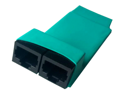
Figure 2. Cascade Temperature Sensor External View
The temperature sensors are connected using the standard patch cords or CAT5/5e UTP cross patch cords used to build local computer networks. The patch cord can be from 0.5 to a few tens and even a few hundreds of meters long.
When the chain with very long connections (up to several hundreds of meters) is being built then an intermediate power/interface unit and power supply shall be additionally installed.
The current temperature values can be obtained from the sensors in two ways:
- Through Web interface featuring the tab with the temperature values (up to 25 sensors).
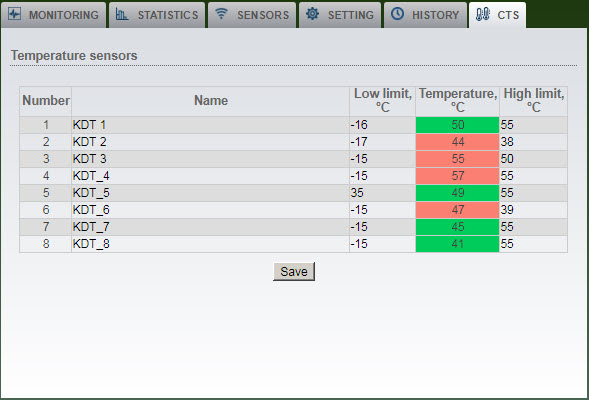
Figure 3. Web Interface – Cascade Temperature Sensor Tab
- Using SNMP-based connection to the monitoring system. In this case the temperature values can be obtained from as many as a few hundreds of sensors.
Multipoint Temperature Measurement System allows to enter high and low temperature limit values as required for each connected sensor providing the option to issue SNMP trap message when the limits are exceeded. Information specifying that the limit temperature values have been exceeded is stored in nonvolatile memory of TTA-08.
Key Specifications
Operating range of measured temperatures: from -40°С to 120°С.
Permissible absolute accuracy limits:
- ±0.5°C typical accuracy @ 25 °C
- ±1.0°C in 0°C-70°C range
- ±1.5°C in -40°C-120°C range
Power consumption: 3W.
Supply voltage: 20-70V.
Dimensions of system units:
- TTA-08 controller: 150х100х40 mm
- Cascade temperature sensor: 80х35х15 mm
Average lifetime: 10 years at minimum.
Advanced Functionality
Multipoint Temperature Measurement System is not limited to measuring temperature. Its application can be significantly expanded by using optional products.
The following sensors for monitoring the standard security equipment can be connected to TTA-08 access control unit:
- motion sensor
- broken glass sensor
- window/door sensor
- smoke sensor
- flood sensor
TTA-08 monitoring and control unit features 2 inputs designed to connect 220V AC voltage detection sensors and one input designed to measure battery voltage.
Battery voltage is measured within a range from 0 to 90VDC with +/- 1V accuracy.
The system software allows to assign high and low battery voltage thresholds for alarm reporting (SNMP trap, sound or visual alarms).
Application Range
Using Multipoint Temperature Measurement System allows to create multiple comprehensive solutions for controlling and monitoring temperature modes of remote facilities:
- Temperature mode measuring system for data processing centers and server rooms.
- Temperature monitoring and measuring system for:
– industrial premises
– storehouse facilities
– pharmacy premises
– food production and refrigeration facilities - Temperature monitoring and measuring system for telecommunications facilities using GSM and LAN networks.
SNMP-Based Network Control and Monitoring System
The network device monitoring system “TTA Monitor” is a complete solution using the SNMPv2 protocol.
“TTA Monitor” application is an additional option of the multipoint temperature diagnostics system designed for network management and monitoring of several objects at the same time.
The application uses the SNMP v2 protocol or an internal communication protocol to communicate with devices.
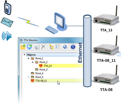
Figure 4. SNMP agent “TTA Monitor” is a solution for simultaneous monitoring of multiple monitoring devices.
In addition to standard visual and audio information when using a USB device of a GSM gateway, the user of the additional system gets the opportunity to organize emergency telephone auto-informing and SMS messages.
“TTA Monitor” software can work under Windows and Linux operating systems.
“TTA Monitor” application has a standard multi-window interface, which is the main form with opening child windows.
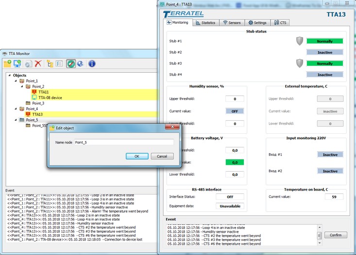
Figure 5. TTA Monitor Application Interface
All monitored system devices are displayed as a tree within the main application window.
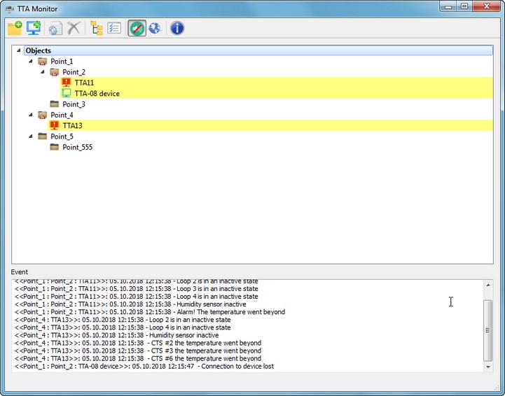
Figure 6. TTA Monitor – Device Tree
Each connected device has parameter monitoring and configuration forms implemented for the device itself and its connected sensors.
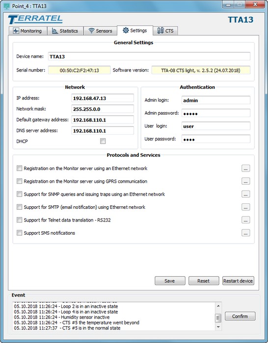
Figure 7. TTA Monitor – Device Parameters
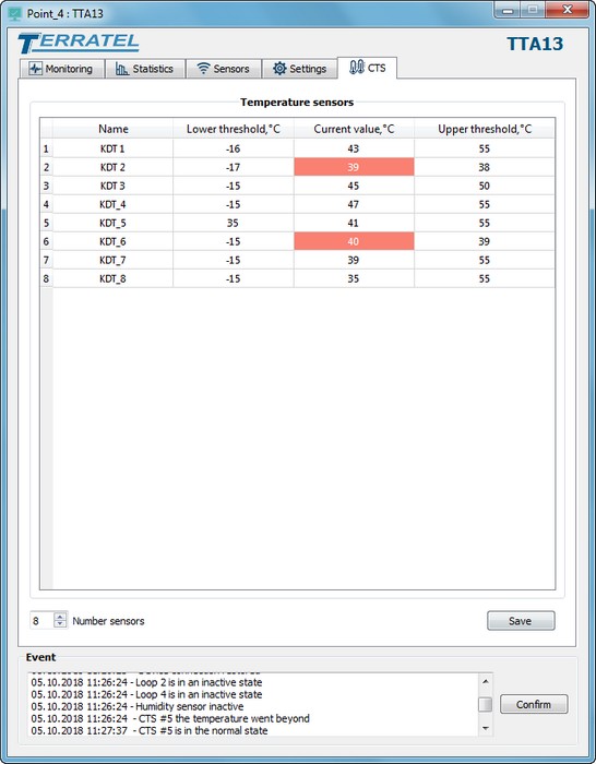
Figure 8. ТТА Monitor – Cascade Temperature Sensor Configuration and Monitoring
Staff Benefits
Remote object monitoring will allow the operator to find correct solutions in emergency cases, instruct the staff accordingly, switch systems remotely or change settings of the devices and connected sensors.
Optional products will allow to monitor fire safety of the facilities, prevent them from intrusion, monitor 220V AC availability at the facilities and monitor battery voltage.