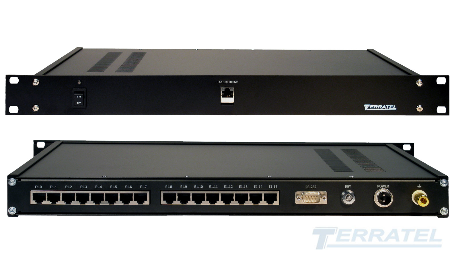
Support of Digital TDM Switch and E1 PCM Multiplexer Functions

Features
- from 2 to 16 E1 interfaces
- SS7 (supporting subsystem MTP2, MTP3, ISUP)
- PRI (DSS1, QSIG, Q.931 protocols)
- V5.2, R2 MFC, R1.5
- SIP, hardware echo cancellation (option)
- full accessible commutation 16 E1
Overview
Signaling Converter is the powerful tool used to interface the telecommunications equipment and provide its interaction using various signaling systems.

Pic 1. Signaling Converter Connection Diagram.
Using signaling converters helps to optimize capital expenditures when upgrading the network and extend the lifetime of the existing systems.
Key Features
The signaling and PCM protocol converter provides:
- converting signaling protocols of PCM30 digital links
- creating semi-permanent connections
- dividing E1 links into channels
- converting the subscriber number when the connection is being established over the assigned masks
- visual monitoring of how system information flows in signal channels
- full-service switching of 16 PCM links
Signaling and protocol converter fully supports full-access and non-full-access switching modes.
Signalings, Protocols and Interfaces PSTN
Signaling Converter supports the following signaling protocols:
- SS7 (or Signaling System #7, CCS7 Common Channel Signaling System 7, C7, CCITT7, N7 Signalisierungssystem Nummer 7)
- ISDN PRI (or Euro-ISDN, EDSS1, DSS1, QSIG protocols, recommendation Q.931)
- V5.2
- R2 MFC
- R1.5
- SIP (option)
Non-full-access switching mode
This switching mode allows to organize such connection of connecting lines, in which only a part of the outputs is available to each input of the switching system.
An example of such use of the Signaling and Protocol Converter from Terratel is switching 10 E1 streams with PRI signaling into 4 E1 streams with SS7 signaling. In this case, conversion in PRI – SS7 – PRI modes or PRI – PRI switching can be provided.
The use of an incompletely accessible switching scheme enables the Communication Service Operator to optimize the number of Trunk lines on one of the parties.
Applications
The equipment will realize converting of signaling in different configurations:
- ISDN PRI to SS7 Signaling Converter
- R2 CAS to SS7 Signaling Converter
- ISDN PRI to R2 CAS Signaling Converter
- CAS to SS7 Signaling Converter
- SIP to SS7 Signaling Converter
- SIP to ISDN PRI Signaling Converter
- SIP to V5.2 Protocol Converter
Design and Management
Technically, the product is designed as a dedicated industrial controller based on the state-of-the-art telecommunications processor. The Signaling Converter is designed to be installed in a server closet 19″ rack with 1U height of the housing.
Monitoring and control (changing configuration, monitoring operation etc.) are performed locally (RS-232 interface, COM1 port) or over Ethernet (TCP/IP).
Monitoring the operation of the device and reporting of accidents is carried out using the SNMP protocol.
Electrical power supply
The power is supplied from the DC source operating within from -36V to 72V range or from the AC source operating within from -90V to 265V range.
AC/DC redundancy power supply support. Power redundancy can be provided by installing two power sources that are operated concurrently with various configurations: AC 220V+AC 220V, AC 220V+ DC 48V/ DC 60V or DC 48V/60V+DC48V/60V.