What is a DC/DC converter or principle description of operation of DC/DC converters used to build power sources
DC/DC power converters are widely used in various electronic appliances, computing tools, telecommunications units, industrial control systems, mobile devices etc.
DC/DC converters are used either to increase or decrease output voltage with respect to input voltage.
DC/DC Converter Types
There are various types of DC/DC converters available on the market today.
- Non-Inductive DC/DC Converters
To power low-powered loads it is useful to use converters based on switching capacitors. Using these converters does not require expensive wire-wrap components, which allows to develop affordable and compact power supply units. Such converters can have both fixed and adjustable voltage.
- Inductive DC/DC Converters
Converters without galvanic isolation between input and output are widely popular. This converter features a single isolated power supply. Depending on the position of the key voltage can be increased, decreased or inverted to reverse polarity voltage. The key components are often insulated gate bipolar transistors (IGBT) and field effect transistors (FET) of various types.
Inductive converters are of the following types:
- Down pulse converter. The key here is the transistor controlled with the pulse-width modulator.
- DC/DC up pulse converter. Its features are described below.
- Converter with adjustable output voltage. These converters allow to have both higher and lower output voltage. What do we need them for? As an example they can be used in products with voltage set by a lithium-ion battery. As time goes by the battery slowly discharges and its voltage reduces but using this converter allows to continuously maintain the output set point.
- Converter with any output voltage. These converters are able to generate both higher and lower output voltage. What do we need them for? As an example they can be used in circuits with voltage set by a lithium-ion battery. They feature 3.3V voltage. In due course of operation its voltage reduces, which makes sense to convert it to 3.3V at the output. The example of such converter is Buck-boost DC/DC converter from Terratel.

Pic. Key Parts of DC/DC Converter
- Galvanically Isolated DC/DC Converters
These converters use pulse transformers with multiple coils, which allows to eliminate communication between input and output circuits.
These converters feature a big voltage difference between input and output voltages. For example they are used in power supply units of pulse photoflashes that have the output voltage of about 400V.
DC/DC Converter Operating Principle
So our current voltage is 5 volts and we need to convert this to a higher value. There are several options to do this. One option is to charge capacitors in parallel and then to switch them in sequence. This should be done very quickly, several times a second. In practice, this is not possible to achieve and as such dedicated DC/DC converters are used to solve this problem.
To understand how this converter works let’s imagine we are plumbers.
Phase 1 – Turbine Acceleration
First we need to accelerate the turbine. To do this the throttle opens and water discharges quickly transferring part of its energy to the turbine and as a result the turbine starts rotating.

Phase 2 – Filling Pressure Storage Tank
The throttle closes. A portion of the water pushed by the rotating turbine flywheel half opens the valve and fills the storage tank. Another portion of the water heads to the consumer under high pressure provided by the storage tank. At the same time the valve prevents the water from reversing.

Phase 3 – Generating Power from the Pressure Storage Tank and Accelerating the Turbine.
The speed of the turbine starts falling. The water cannot push the valve anymore and the storage tank still has enough energy accumulated. Then the throttle opens again and the water starts rotating the turbine quickly. The flow of the energy heading to the consumer does not stop since the consumer receives it from the storage tank.

Then the cycle repeats.
Now that the operating principle is clear we’ll switch from plumbing equipment to electronics.
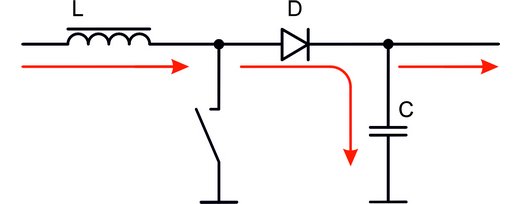
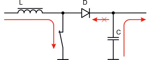
We have got the inductive throttle in place of the turbine. The transistor is used in place of the throttle that controls the water flow. The diode acts as a valve, and the capacitor is used in place of the pressure storage tank.
This is how DC/DC converter looks like. How does it work? Pretty much the same.
Phase 1 – Inductance Accumulates Charge
The key is closed. Inductance accumulates energy by receiving current from the source.

Phase 2 – Transferring Energy to Capacitor
The key opens and the coil keeps accumulated energy in the magnetic field. Current tries to stay at the same level but the additional energy from inductance raises voltage thus opening the path through the diode. Some part of the energy heads to the consumer while the remaining energy is accumulated in the capacitor.

Phase 3 – Accumulating Energy in Inductance and Transferring a Charge to the Consumer
The key is locked then, and the coil starts accumulating energy again. At the same time the consumer receives energy from the capacitor.

