Remote monitoring, control and management of technological equipment at remote sites

Features
- TCP/IP Monitoring and management, SNMPv2
- 2x 10/100 Mbit/s Ethernet Interfaces
- 2х RS-485 Serial Ports
- 4х RS-232 Serial Ports
- 8х Discrete (Digital) Inputs
- 4х Relay Contact Outputs up to 10A
- 4x Analogue Sensor Inputs
- 2x Temperature and Humidity Analogue Sensor Inputs
- 1х Digital Temperature Sensor Input
- Power Consumption Up to 5W
- Support 220 VAC External Power Supply
- 20 VDC – 70VDC Operational Power
Overview
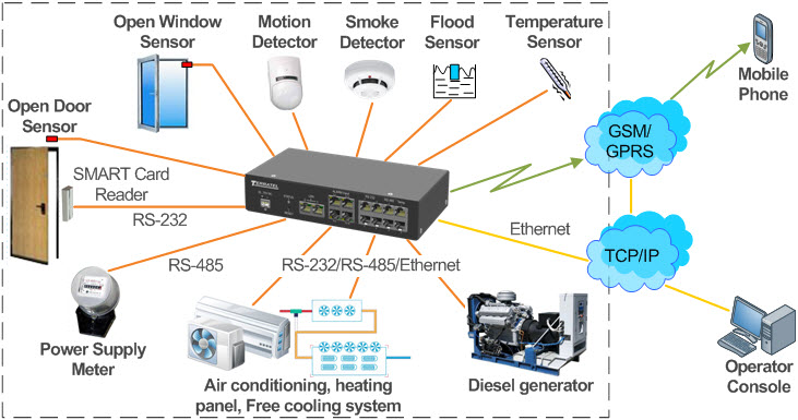
TTA-X is designed to monitor, manage and control remotely multiple processing units installed on remote unattended sites over Ethernet.
Specifically the unit allows to:
- transfer data from security/fire alarm units
- transfer data from video surveillance units
- monitor and control power supply and climate control units
- monitor and control dedicated processing units
- monitor environmental parameters
- capture and transfer alarm messages
- generate messages on exceeding set values of control parameters

Figure 1. Application of a remote access and monitoring device TTA-X.
ТТА-Х remote monitoring, control and management unit features in its basic configuration 4x RS-232 serial ports, 2x RS-485 serial ports, 2x temperature and humidity analogue sensor inputs, 4x normally open dry relay contact outputs, 8x digital outputs, and 4x inputs to connect multiple analogue sensors.
The sites where more parameters should be monitored may require to retrofit the base version of the unit with the required expansion modules.
Monitoring, remote control and data collection are performed using SNMP version 2.
Hardware
The unit is a modular structure in a 1U housing. Base TTA-X-BASE unit includes a power converter, main microcontroller, basic interface set and expansion connector.
The base unit provides connection of expansion modules when required.
The operation temperature ranges from -40°C to +85°С.
Rated supply voltage: 20 VDC – 72 VDC.
The remote access and monitoring unit is connected to the data transfer network using Ethernet interface. Two peer 10/100 Mbit/s Ethernet ports connected using RJ 45 connector provide reservation of data links.
IP address, the mask and the gateway can be set up both automatically using DHCP and manually.
Software Features
Main features of the unit software include:
- Receiving required information about the situation at the site (diagnosing technical condition of the communication and processing equipment, electricity meters, power systems, temperature range support equipment (air conditioner, heating appliances), supply and exhaust air cooling systems (freecooling), some other units and devices etc.)
- Autopolling devices, equipment, units and their respective parameters at predetermined intervals and storing required information about operation of the site during a long period of time.
- Automating the process of collecting, processing, storing, and displaying information about the use of power.
- Accumulating, processing, storing in the database and documenting accounting parameters for each accounting record.
Creating users, editing rights, blocking users, changing passwords etc.
Exchange Protocols
The unit supports SNMP for reading and writing. SNMP allows to read current configuration and set up all configuration parameters of the unit (setting up ports, data links etc.), read data from the temperature sensors (set up temperature alarm thresholds), monitor the condition of external alarm contacts, set up contact pairs (normally closed, normally open, alarm name, active/inactive etc.)
When an alarm event occurs/disappears (alarms from external devices, alarms upon exceeding temperature thresholds etc.) trap messages can be sent over SNMP to assigned IP addresses.
External Device Support
The remote access and monitoring unit can support multiple types of external devices including the following:
- power supply meters (meeting IEC 62056 (DLMS / COSEM) standard related to data exchange with external devices)
- power racks
- control panels of diesel generator plants
It is allowed to add new types of equipment from multiple manufacturers. To configure them and exchange data it is required to provide documentation for the exchange protocol of the respective equipment.
It is also allowed to work with the devices using the software from the suppliers of power system equipment, meters, and diesel generator plans. To do this the selected channel that provides communication with the unit (RS-232, RS-485) appears in Windows as the virtual serial port (COM port) or Telnet port. If Control button is selected on the selected device then the software from the manufacturer of the equipment will be launched that can connect to the unit via the indicated port.
The unit is transparent in Ethernet – RS-232 bridge mode i.e. it provides the direct data link for the third-party software.
The unit provides reading and transmitting the operation parameters of the equipment over SNMP to the monitoring system.
Automated climate control can be provided based on the preset temperature thresholds. If the temperature drops below the lower threshold then the heating equipment turns on and the air conditioner turns off (adjust for hysteresis). If the temperature rises above the upper threshold then the air conditioner turns on and the heating equipment turns off (adjust for hysteresis). Temperature thresholds that turn on/turn off the respective devices are set up separately for heating and cooling devices. When the warning or critical upper or lower temperature thresholds are crossed the system sends alarm messages to the server software and assigned IP addresses over SNMP.
Serial Ports
To poll/control external equipment over serial ports the unit features 4x RS-232 and 4x RS-485 ports in their minimum configuration. The number of ports can be expanded by applying expansion cards.
The ports are software configurable and each port provides connection via dedicated RJ 45 connector.
Discrete (Digital) Inputs
The unit can receive alarm signals that are sent from alarm sources using dry (relay) contacts or optoelectronic decouplers. Input alarm lines are software configurable to be closed/open or deactivated.
Rated voltage from the unit on open pairs of input alarm lines is 12 VDC.
All alarm input lines have the common bus. Galvanic decoupling is not provided in the unit (it is provided by alarm sources).
There are 8 input line pairs in the basic configuration and this can be increased by using the expansion cards with 16 lines on each card. Input is provided using RJ-45 connectors with 4 inputs per connector.
The unit has ports designed to connect 2 temperature sensors or combined temperature and humidity sensors. The unit polls these sensors, sets up the alarm threshold values (minimum temperature, warning temperature, alarm temperature).
Control Outputs
The remote access and monitoring unit can control external processing equipment by applying normally open dry relay contacts with up to 10A i.e. it can enable and disable other devices.
The basic configuration features 4 outputs (4 pairs of normally open relay contacts).
Modularity
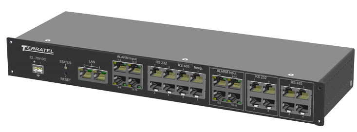
The unit is a modular structure in a 1U housing that should be placed in a rack. It is based on TTA-X-BASE base unit that includes a power converter, main microcontroller, base interface set, and expansion connector. TTA-X-CROSS expansion card is connected to the base unit. This expansion card provides connection of up to 3 expansion modules. As such the number of ports in the unit can be scaled (multiple type additional ports and interfaces can be set in multiple configurations).
The unit is powered either from 18V-72V DC power supply at the customer’s site or from an individual ~220V/50Hz AC/DC power supply unit.

Figure 2. General View of the Unit with 3 Expansion Modules.

Figure 3. TTA-X Structure Diagram – system components.
System Components
Structurally TTA-X consists of the base unit and required expansion modules.
Base TTA-X-BASE unit contains:
- power supply unit operating from 18 VDC – 75 VDC
- high-performance control processor
- flash memory used to accumulate information about alarm events
- 2x 10/100 Mbit/s peer Ethernet ports output from the internal switch (i.e. ports can function as switches when the number of ports is insufficient) TTA-X is remotely accessed and controlled over Ethernet
- 4x RS-232 ports, each port is output to dedicated RJ-45 connector
- 2x RS-485 ports, each port is output to dedicated RJ-45 connector
- 2x digital temperature sensor inputs
- 2x temperature and humidity analogue sensor inputs
- 4x normally open dry relay contact outputs up to 10A
- 8x digital inputs to connect alarm sensors, processing device activation sensors etc. Rated voltage from the unit on open pairs of input alarm lines is 12 VDC.
- 4x current or voltage measurement analogue inputs with 12V pull up and 40 mA closing current to connect multiple analogue sensors.

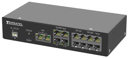
Figure 4. TTA-X-BASE Base Unit
As such the base unit is a complete control system with quite a rich set of interfaces. If this number of interfaces is sufficient for the customer the unit can be supplied in a housing of XXX x YYY x ZZZ cm to be installed on a desk or mounted in a rack. This design does not allow to further expand the number of the interfaces.
Expansion Modules
- TTA-X-4RS232 – contains 4x RS-232 ports, each port is output to dedicated RJ-45 connector.
- TTA-X-4RS485 – contains 4x RS-485 ports, each port is output to dedicated RJ-45 connector.
- TTA-X-8AIN – contains 4x current or voltage measurement analogue inputs with 12V pull up and 40 mA closing current to connect multiple analogue sensors.
- TTA-X-16DIN – 8x digital inputs to connect alarm sensors, processing device activation sensors etc.
- TTA-X-BAT – backup power supply unit. It contains the battery, and charge controller. It is designed to provide temporary backup power supply for the system and notify the control system when the main power cut occurs.
- TTA-X-GSM – GSM based alarm notification unit. You can send alarm messages via Internet over SNMP, email notifications, and SMS messages.
- TTA-X-ETH – Ethernet port expansion module. 4x 10/100 Mbit/s ports connected using RJ-45 connectors. The ports have a common switching field with Ethernet ports on TTA-X-BASE base module.
Other types of modules can be custom designed (such as modules designed to be connected over IoT (Internet of Things) data exchange protocols etc.)
Universal Control and Monitoring System Support
SNMPv2 support allows to integrate TTA-X in the standard network control and monitoring system. For example you can use multiple open source solutions for distributed monitoring of the network equipment. These universal solutions with the open source code are designed to monitor multiple network devices in real time and ensure that the notifications are received when any problems occur.
We also offer our dedicated proprietary software TTA Monitor.
TTA Monitor is a cross-platform software that can operate under Windows or Linux operating systems.
Technical Specifications
| System Type | |
|---|---|
| Unit |
| General Info | |
|---|---|
| Length 15 cm/5.905″ | |
| Width 10.8 cm/4.251″ | |
| Height 3.9 cm/1.535″ | |
| Weight 400 g (without the aerial, battery and set of sensors) |
| Interfaces | |
|---|---|
| Ethernet 10/100 Mbit – 2 | |
| GSM/GPRS – 1 | |
| RS-485 galvanically decoupled to 2kV – 2 | |
| RS-232 galvanically decoupled to 2kV – 2 |
| Connected Devices and Monitored Parameters | |
|---|---|
| Loops for connecting security/fire alarm devices – 4 | |
| Power supply output of security/fire alarm devices (10..12V, 100mA or 10..15V 750 mA) – 1 | |
| Remote temperature sensor connection input – 1 | |
| 0..3V voltage metering input (humidity sensor) – 1 | |
| Temperature sensor power supply output (5V, 100mA) – 1 | |
| 0..90V voltage metering input (station battery or UPS battery) – 1 | |
| Inputs for connecting 220V AC voltage availability detectors – 2 | |
| Input for connecting a backup battery of 12V rated operation voltage – 1 |
| Event Memory | |
|---|---|
| Nonvolatile memory for keeping 65,536 events | |
| Nonvolatile memory for keeping 131,072 events (optionally) |
| Supported Protocols | |
|---|---|
| TCP/IP | |
| SNMPv2 |
| Power Supply | |
|---|---|
| Input supply voltage range | from 20 to 70V DC 3..4W (without GSM module) 4..5.5W (with GSM module) |
| Power consumption | up to 20W in the battery charge mode |